Tuesday 29 March 2022

AJS 33/7 Trophy Model Restoration: The Cambox

Before continuing with the camshaft drive, ie chains, sprockets, Vernier adjusters, Weller tensioner etc.  I really needed to check that all was OK in the cambox …and fix anything that wasn’t.

The picture below shows the cambox before stripping

I immediately noticed that it was nearly impossible to rotate the rockers because they were so tight and there were 2 small screws that appeared to be inserted through the rocker spindles.

I removed the rocker spindle screws and found that they were actually threaded taper pins. This is not an AJS fitting and had presumably been inserted by someone to stop the rocker spindles rotating in the cambox casing.


The picture below shows the myriad of bits and pieces from the stripped cambox.

Apologies for using a page of the Sunday Times as a background; it doesn't help clarity.

A few other points were noted:

Someone has gone to a lot of trouble to replace the rockers skids (these are the hardened “ends” that bear on the cam) and new ones had been beautifully made and engraved “IN” and “EX”.

The rockers had been polished and re-bushed – but not reamed to size, which is why they were so tight on the (original) spindles.

The use of taper pins to lock the spindles is really the wrong solution to the problem. This was remedied by making new spindles (silver steel oil-quenched at 815C and then tempered at 230C) that were exactly 0.500” rather than the originals which were 0.499” to provide a good tight fit in the cambox body and reaming the bushes to give the proper fit of the rockers on the new spindles. New deep groove ball bearings (which would have been fitted originally) were also acquired to replace the 2-row self-aligning bearing and the roller bearing that had been used on the camshaft itself.

There should also have been end caps on the ends of both rocker spindles (my R10 and K7 both have these) as a spindle could, theoretically, fall out of the end of its hole in the cambox. The original spindles were threaded to accept these but the end caps themselves were missing. 4x new end caps were therefore made and also 4x reduced hex head 3/8” BSF bolts to allow a spanner to be used in the restricted space where the bolts are inserted. All were chemically blacked prior to fitting.


The cam had been reground and was in excellent condition.

For some reason, somebody had drilled a hole in the top cover of the cambox and fitted a brass union.


This would serve no purpose whatsoever; there is already a targeted oil feed that provides oil to an annular chamber which, in turn, feeds into a drilling in the camshaft through to the cam lobes; there is an oil scavenge drain at the bottom of the cam chamber which is connected to a scavenge pump driven by the camshaft and there is already a breather in the inner timing case. This superfluous non-structural hole was therefore blanked off using Devcon aluminium putty.


Finally, new felt strips were inserted into slots above and below the rockers and a gasket made for the top cover. The felt strips help to prevent oil that is thrown around by the cam from exiting the cam box and pouring out of the ends onto the cylinder head; in my experience these are only partially successful. 


Before bolting the cambox down it is vitally important to check that it "sits" properly on the top of all 4 threaded cylinder head studs. If there is any sign of rocking then this must be remedied to avoid putting a bending load on the cambox structure that could result in it cracking. There are 2 possible ways of addressing this; the first (and easiest) is to insert a shim between the top of the appropriate cylinder head stud and the cambox; the alternative is to adjust the lengths of one or more cylinder head studs (bear in mind this is typically ~0.005” maximum) to eliminate the rocking. I carefully measured the lengths of the existing studs and found that there was already a few “thou” difference between each and by selectively assembling these I could completely eliminate any rocking. The studs are now numbered 1 through 4 so that I know which way to replace them in the future. 

Refurbishment of the cambox is now complete and it can temporarily be put back onto the engine for setting up the chains, sprockets, Weller tensioner et.

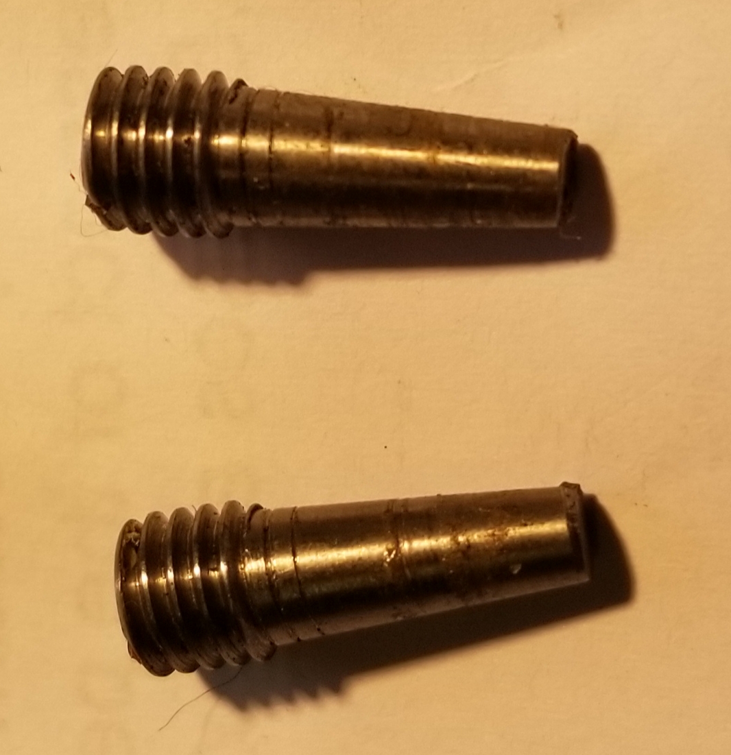
And, finally, a bit of "nerdy" information. AJS stamped their company moniker on a number of major components, such as the oil pump, but they even did this on items such as a simple bolt head. This is a picture of one that I removed from the engine and was used to bolt down the cam box onto its support pillar.


Thursday 10 March 2022

The AJS 33/7 Trophy Model Restoration: Engine Plates

Although the bike had come with the engine and gearbox in place, it had been immediately apparent that new rear engine plates would be needed. Apart from anything else, the plates fitted to the bike had been made to fit the Burman BAP gearbox and I planned to fit the correct Sturmey Archer ‘box.

I drilled an additional hole at the bottom of the engine plates to check the positioning of the SA EIV gearbox to ensure that it would actually fit OK.

Plenty of space ...unlike the V-Twin where I had to fight for every millimetre.

I had also found that the “fit” of the engine plates was poor – quite a bit of leverage was necessary to get them to fit at all. The reason for this is quite simple: the positioning of the holes was not accurate; the distance between the rear 7/16” holes was 0.030” out of position. It might not sound much but this amount is more than sufficient to make it nearly impossible to get the stud through the frame and plates. Secondly, it turned out that the width of the engine, shown below as being 3.57’’


was  0.092’’
greater than the width of the upper lug on the frame


The measurement on the lower part of the frame lug was the same. One would have expected the dimension across the engine and the frame to be the same, within a few “thou”, and I really have no idea how this could happen unless there was something of 0.046” thickness that was originally positioned between the engine plates and the frame on each side that would take up this amount of clearance, but I can’t imagine what that would have been. Manufacturing error? It’s hard to believe that the Collier brothers would have been this sloppy in making one of these top-of-the-range bikes. Did someone reduce the width of the frame lug at some time? I doubt it ....why? Another of life’s little mysteries….

Whoever made the engine plates that were in the frame had recognised this problem and milled a whole section at the crankcase-end of both plates to reduce their thickness to compensate for the difference.


I planned a much simpler solution than this.

The first step was to order 2 pieces of 300mm x 300mm x 6mm steel plate and using the original as a rough template for the profile, to mark out the shape with white paint.


Some modifications were made to the original shape by increasing the height to accommodate the upper gearbox mount and simplifying the internal contour. Each plate was then cut out using the plasma cutter and after removing the slag from the cut edge, the two plates were clamped together to clean up the edges on the milling machine.


The external rounded corners and edges were cleaned up with a flapper disc.

The centre-to-centre distance of the rear engine plate frame-mounting holes was measured accurately with the Vernier by inserting 2 pieces of 7/16” ground bar into the frame lug holes and then using the DRO on the milling machine to position the holes for drilling. The 3x 3/8” holes for the engine mountings were drilled in-situ with the engine mounted securely in the frame and with the rear plates bolted up rigidly to the frame mounting.

After drilling the lower gearbox mounting hole for the pivot, the upper slot – which needs to be at a radius of 7.75”, was machined by mounting the plates on the rotary table and rotating the plates to give the correct arc.


Finally, to accommodate the difference in width between the engine and the frame I found stainless steel washers that were exactly 0.046” thickness and silver soldered these on the inside of the plates to get the same clamping thickness when assembled. After grit blasting to clean up the black steel surface from the rolling process during manufacture and flux from fixing the spacing washers the plates were ready for first assembly into the bike.

I also decided to make new front plates to eliminate some of the additional weight-saving holes that had been introduced and all the existing studs were replaced with new ones made from EN24T.


A new magneto platform was made and a reconditioned BTH racing magneto fitted.

This magneto is not as tall as the one that came with the bike and I had already checked that it avoids interfering with the bottom of the carburettor.

The last job was to make spacers to position the gearbox in the correct place and to firmly clamp it at the top and bottom. A spacer has also been inserted between the upper gearbox support lugs to avoid a large bending load on the lugs that would inevitably result in them cracking.


There will be some further work on the engine plates at a later date for the footrests and primary chaincase but, for the moment, this is sufficient to set up the primary drive and the internal magneto and camshaft drives.