
Anyone reading my blog might wonder why I have devoted so much space to talking about the camshaft drive. The reason is quite simple: there was a lot of work involved and I’ve had to recreate most of the drive and remake many of the components.
At this stage, the main gear/sprocket assembly for the camshaft drive has been remade, the cambox has been rebuilt and the magneto has been replaced by a rebuilt BTH racing magneto sitting on new engine plates and mag platform. The remaining jobs to complete the camshaft drive are:
1) New Weller chain tensioner blade and spring
2) Magneto and Camshaft drive chains
3) Vernier adjusters for both the camshaft and magneto
4) Check the oil pump
5) Repair some minor damage to the inner and outer timing cases
6) New connecting pieces for the oil pumps
This is the 4th bike for which I’ve now made the complete camshaft/magneto drive system and the company that makes my springs, Alberta Springs , has made chain tensioner springs for all of these. The (new) springs that had come with the bike were 1 ½” too short and new ones were therefore made of the correct length.

The short blade that had come with the bike had also not been set up correctly and new pins, which hold the tension spring in place and also position the blade correctly, were therefore made.

In the above picture, the location of the groove in each pin is important and also the short (in this case 0.028”) larger diameter section on the end of the left pin (which is the upper pin when in the engine) to ensure that the blade is positioned correctly with respect to the blade guide support (which is located approximately midway) and that the blade is aligned with the chain run.
This is clearer when the blade is mounted in the engine.

Although Vernier adjusters had come with the bike I couldn’t use them. The magneto Vernier adjuster had been set up for an earlier BTH magneto that used a bolt in the centre of the shaft to secure the sprocket rather than the 3/8” BSF threaded end that became standard in later years. The Vernier adjuster that had been made for the camshaft was, in my opinion, not sufficiently strong to support the loads experienced in driving the camshaft in the respect that the pin that passes through the sprocket and the hub was too small and not sufficiently strongly attached to its washer. The hub was also a loose fit on the camshaft.
A new set of Vernier adjusters was therefore made, which includes the supporting hub and is now a press fit on the camshaft.

These are identical to those made previously for the K7, AJcette and V-Twin. The hubs are made from EN24T; the sprockets are made from EN8 and are a bought-in item and machined to fit (it’s not necessary to machine all the sprocket teeth) and the 3/16” diameter pin and washer are mild steel with the pin both threaded and (on the reverse side) silver soldered together. The keyways are spark eroded.
There are 17 holes on the hub and 16 holes on the sprocket which gives a setting accuracy of 360/(16 x 17) = 1.30 of magneto (or camshaft) rotation which equates to 2.60 of crankshaft rotation.
There are 2 oil pumps on this engine. The larger main oil pump (feed and scavenge) is driven from the end of the magneto/camshaft drive shaft by a 0.25” AF square drive. These externally-mounted reciprocating AJS pumps are extremely rare and, as far as I am aware, are only fitted to the OHC AJSs; I have never seen one come up for sale second hand. Before fitting to the engine I stripped the pump to check the internals:

which were found to be in excellent condition.
Unfortunately, the outer timing case was not in such good condition around the region where the oil pump is attached.

The pump is positively located with a spigot that fits into the larger diameter hole in the centre of the picture and is secured with 2 screws either side. It can be seen in the above picture that one of the securing holes is severely elongated and, although it can’t be seen in the picture, the thread in the other hole is very worn. There are also 3 additional holes that have been drilled in random places (one is hidden behind the pump in the picture); I have no idea why these holes are there – they shouldn’t be!
The obvious repair to the threaded holes would be to fill them with weld and then retap. However, the main reason why I didn’t go this route is that the section of the casting here is not very thick (around 6mm) and I choose an alternative that was to make a block of 10mm thick 7075 T6 aluminium the same oval shape as the front face:

The block was then clamped to the main timing case casting and positively located with a dowel inside to ensure that the holes in the block and casting were concentric (this is very important for alignment of the oil pump drive):

The block was then laser welded by EMP tooling to the main casting on the outside, the clamp and dowel were then removed and the internal joint was laser welded and the superfluous holes were filled:

Finally, the threads were retapped


Unfortunately, this part of story does not end there.
When I tried to assemble the collection of parts on the engine I found that there was no way that the lip, that positively locates the oil pump onto the timing case, would fit inside the hole of the new aluminium block with the connecting piece in place. A measurement (made in 2 different ways) indicated that the camshaft drive shaft was not concentric with the hole – there was ~0.045” difference in their centres.
I have no idea how this could happen: the cassette assembly that holds the shaft is positively located to a depth of ~0.5” into the timing-side crankcase and held with 5x 3/16” screws; the inner timing case is attached with 7x 3/8” BSW screws – it is rigidly fixed and cannot move; the outer timing case is held on with 21x 2BA screws and, similarly, it can only be attached in one position; the attached block was set up with a close-fitting dowel to the original hole to ensure both the original hole in the timing case and the new hole in the block were concentric prior to laser welding.
As the saying goes, “S**t Happens!” Having gone to a lot of trouble to set this up accurately, I was really not happy.
Anyway, how to sort it out? My first thought was to make an Oldham coupling. Oldham couplings have been around for many years and, on vintage motorcycles, are most notably used by Velocette and Norton for their OHC engines from the 1920s onwards to connect the lower and upper bevel drives for the camshaft. Oldham couplings allow 2 degrees of freedom and were invented to connect misaligned shafts and can be used where there is substantial misalignment. I even made an Oldham coupling and tried it in position:

It would probably have worked – the pump rotated freely with it in place, but doing this does not address the fundamental problem of misalignment and a better solution is to solve the problem itself rather than inventing a workaround.
I therefore removed the new block of aluminium with a slitting saw on the milling machine

and after cleaning up the faces, repositioned it using a 15mm diameter steel rod through the bearings in the cassette and a 15mm hole bored through the dowel and then tacked the block and casing together with the TIG welder.

After laser welding the two components together (again!) the pump now fitted perfectly with the connecting piece in place.
It was now time to turn attention to the cambox scavenge pump at the top of the timing case.
There is only a short distance between the end of the camshaft (which has 7/16” x 20TPI thread) and the oil pump. Somebody had previously made a nut with a sliding piece which is, effectively, half an Oldham coupling on the end to engage with the ¼” square drive on the oil pump. Although it had been well made, this would not work; if the camshaft and oil pump are out of alignment then 2 degrees of freedom are required in the movement of any coupling used to correct the misalignment. One degree of freedom is not sufficient.
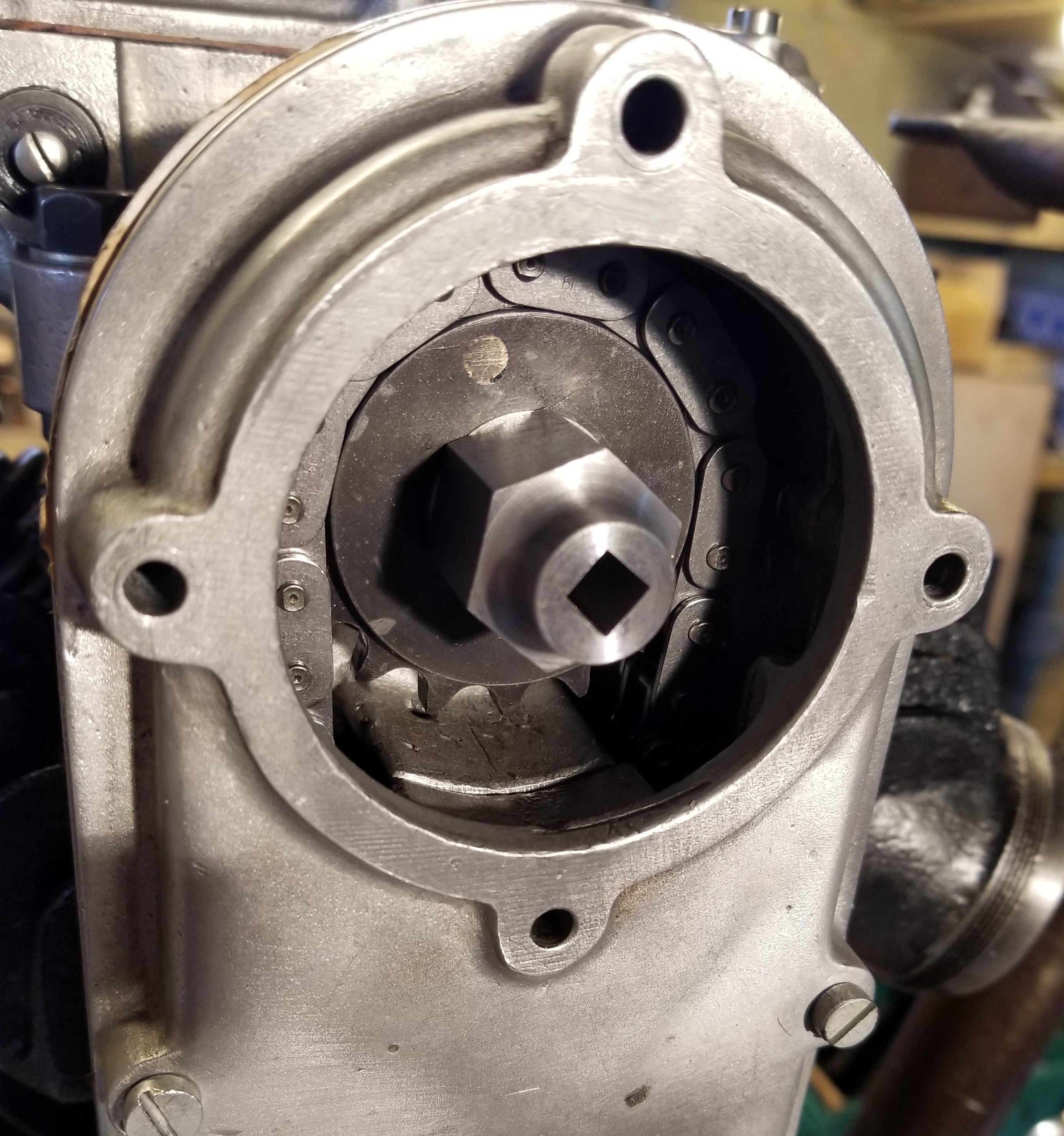
On this occasion, luck was on my side; the camshaft and oil pump were in alignment. There was insufficient distance between the end of the camshaft and the oil pump to insert a connecting piece and so a new nut with a square hole was made into which the oil pump drive could be inserted directly.

The new nut is shown on the above left in the picture whilst the one that came with the bike with its sliding piece is shown below it.
The collection of bits and pieces, together with new endless chains, could now be assembled

And with oil pumps that are in the right place with their associated connections to shafts. This is still a dry build and lock-wiring will be used for the final assembly.

When I started work on this part of the engine I had hoped that I would be able to use the parts that were already there. In practice, the only parts that I have retained are the cassette castings, the Weller blade guide support, the 40 tooth driven gear and new low-friction material that had been fixed to the tension-side of the inner casing; I have had to replace or repair everything else. However, I am now satisfied with the mechanical integrity of the whole timing-side setup and I would not anticipate problems here in the future.
Anyone reading this blog in detail might wonder why I document things that go wrong. After all, it would be so much easier to simply report only the good outcomes. But this is not the reality of life; in spite of one's Best Efforts things go wrong from time to time and, hopefully, we learn something from the experience and gain a little more knowledge. As the saying goes, hindsight is a marvellous thing.