
The powder coating and chrome plating came back from their respective suppliers towards the end of January and work started on reassembly. However, I didn’t get far before my wife and I set off on a trip to Kenya that had been planned way back in 2022.
The trip involved safaris in 3 different national parks (Masai Mara, Lake Nakura and Amboseli, adjacent to Mt Kilimanjaro) and we spent quite a bit of time travelling by road between these. It is always interesting to observe motorcycling in different countries around the world; in most of Europe, the US and the Antipodes motorcycling is predominantly for pleasure and more often on large capacity bikes whereas, for example, in India or Kenya motorcycles are mostly smaller capacity “workhorses” and are used for transporting the family or goods around. Any visitor travelling on Indian roads will regularly come across a family of 5 astride a small TVS motorcycle.
I came across 3 interesting uses of motorcycle workhorses in Kenya. The first had a very substantial sheet metal folder strapped across the back seat, the second boasted a large 3-seater sofa across the back (I’m not sure whether the sofa was being transported or this was an up-market taxi service) and the third, and by the far the most impressive, was this one.

It is not so easy to see the bike under the Makuti thatching – the dried leaves of the coconut. As we drew alongside the rider is visible

and who just about manages a smile although the guy perched precariously on top doesn’t seem too happy

Looking through a few old pictures recently I also stumbled across this one from a trip to Vietnam.

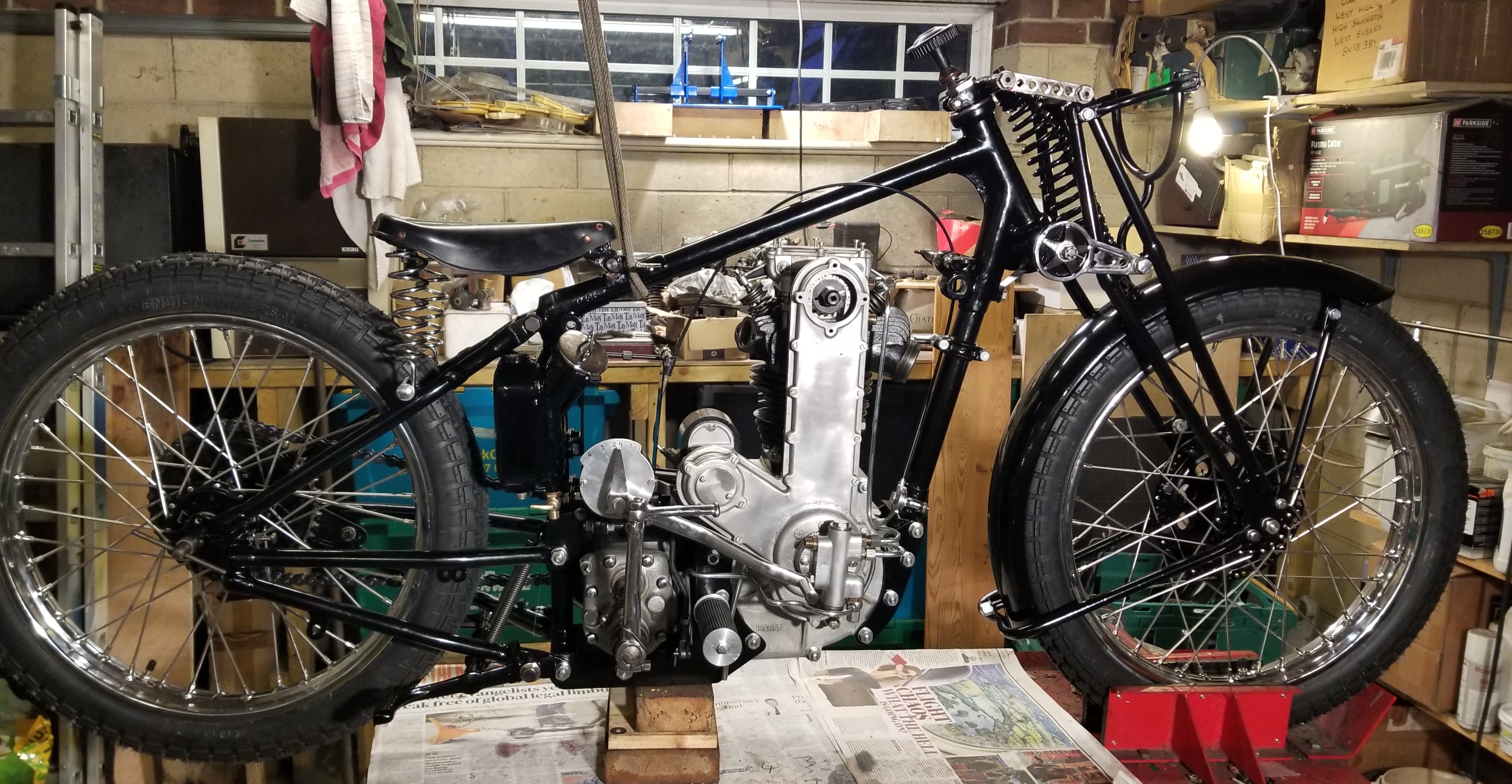
Before setting off for Kenya, I had managed to start reassembly of the bike.
The engine bottom-end was assembled and, together with the gearbox, was inserted into the frame.

The stem for the girder forks has also been attached with new 3/16” balls in the bearing cups.
The inner timing case is fixed and 3x 3/16” studs have been screwed into 3 of the 3/16” BSW threaded holes that support the cassette/bearing housing for the camshaft and magneto drive. The inner part of the cassette is a tight fit in the timing case housing and rather than trying to twist it into position later (and the same with the outer part of the cassette) it is much easier to use these studs to position it correctly on first assembly.

The bottom pivot for the cam chain blade tensioner has zero space on which to get a spanner or a socket and I tighten this using a machine chuck that is usually found in the lathe tailstock.

It is not possible to screw in the tension blade pivot and then insert the inner part of the cassette because part of the thread for the blade pivot is contained in the cassette itself.
Before completing this part of the assembly, the 20-tooth crankshaft pinion was mounted onto the keyed crankshaft.

The outer part of the cassette could now be assembled.

It was now time to set up the valve timing. The 1933 OHC manual gives the following diagram for valve and ignition timing:

From this, I would discern the following:
IVO 200 BTDC
IVC 550 ABDC
EVO 680 BBDC
EVC 250 ATDC
Ignition: 500 BTDC fully advanced
Although both the inlet and exhaust periods are relatively short by modern standards, they are not unreasonable and in any case, I only have one camshaft and the only aspect that I can change is the phasing of the entire cam events.
I set a 0.010” tappet clearance and set crankshaft and camshaft at EVO (crankshaft with a degree marker disc and camshaft vernier adjuster position determined when clearance went to zero) to see what the other timing events would be. This gave measurements of:
IVO 190 BTDC
IVC 600 ABDC
EVO 680 BBDC
EVC 320 ATDC
These are remarkable close to those given in the manual and I decided to stay with this setting.
However, 500 BTDC for ignition timing is far too advanced by modern standards. One has to be careful in interpreting certain information given in manuals of the period and this applies to ignition timing. Why? Well, because fuels used in the 1920s and 1930s had quite different characteristics compared to fuels of today and the optimum engine settings were selected for the fuel that was available at the time.
The following graph gives a lot of insight into the evolution of fuels from the 1920s.
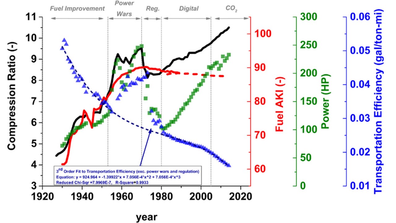
Although this graph is based on data from the US, the trends in Europe would have been similar. There are a number of points of interest that can be gleaned from this graph. Firstly, the red line shows that the fuel AKI (Anti Knock Index) or octane number increases steadily from a value of around 62 in the late 1920s to 90 in 1970 with a particularly steep increase in the 1930s and 1940s. This is extremely important in determining the maximum useable compression ratio and which, in turn, correspondingly increases from 4.5 to 9 over a 30-year period. (note: the US uses AKI = (RON + MON)/2 – the average of two different methods of measuring the octane number whereas Europe uses RON. RON is higher than MON. Nevertheless, the conclusions would be the same).
The purpose of this brief excursion into the evolution of fuel characteristics is to illustrate how this contributed to rapid engine development that occurred during the early days of the internal combustion engine …..and why 500 BTDC for ignition timing would have been OK in 1933 but not today.
I decided to set the timing at 380 BTDC fully advanced. With a compression ratio of 9:1 the engine may knock under low speed, high load conditions but with 30 degrees of manual retard available a good setting will be found and adjustments made if required.
2 new stand springs (I only had one) were made by Alberta Springs


and it took just a couple of days to get something that looked like a reassembled motorcycle.
The oil tank was rubbed down by hand and sprayed with 2k etch primer and 2 coats of gloss black. As I’ve probably mentioned before, I never send oil tanks out to be powder coated because of the risk of grit remaining in crevices inside the tank in spite of ones best efforts to mask every entry point prior to grit blasting and flush out every grit molecule when finished.
There are obviously a few more bits to bolt on and there is still a bit of work needed to finish the petrol tank – painting, gold leaf lining and the “AJS” insignia but the bike is now nearing completion.
No comments:
Post a Comment