Saturday, 11 April 2026

WELCOME to my blog about restoring vintage overhead camshaft AJS and Velocette motorcycles

 Apologies to anyone that has come to this page expecting to see exclusively vintage AJS motorcycles .....scroll down the page a bit and you will find plenty of them.

However, I sent all of my cammy AJSs to Bonhams last year and they were sold at the Autumn Stafford Sale

The URL of "vintageajs" for this blog is now somewhat misleading but it's too late to change it and there is still plenty to read about the AJAY projects. If you happen to be the new owner of one of the bikes that I recently sold then there is plenty here to read about its build. I still have 2 early Big Ports waiting in the wings ....but they will have to wait until I've completed the Velos. 

In 2023 I started the restoration of 2 early Velocette KTTs plus another Mk 1 OHC cammy special - a few details about each of these bikes can be found here and here

A lot of work has been done on these bikes over the past  2 ½ years and the INDEX PAGE provides links in chronological order of the project so far.

In August last year I acquired a DOHC 250 Velo Engine. I have completed the rebuild of this engine and the dry build of this bike is also finished. Details of this projecty can be found in the links in the INDEX page.

Before starting on painting and plating of these 3 bikes I decided to rebuild the engine of KTT 581 in preparation of building it into a bike over the months of next winter.

The bottom-end has been completed - details here


and I'm now working on the top-end - the cylinder head and cambox.

During the last 5 years I have posted quite a lot of information and to aid navigation the "Labels" section on the right side of this page lists the various projects.

The labels marked "INDEX" give a link to a page that provides a complete list and links to all of the separate sub-projects related to that main project.

Alternatively, scroll down this page and see what's here.

When I started this blog I owned a 500cc AJS R10


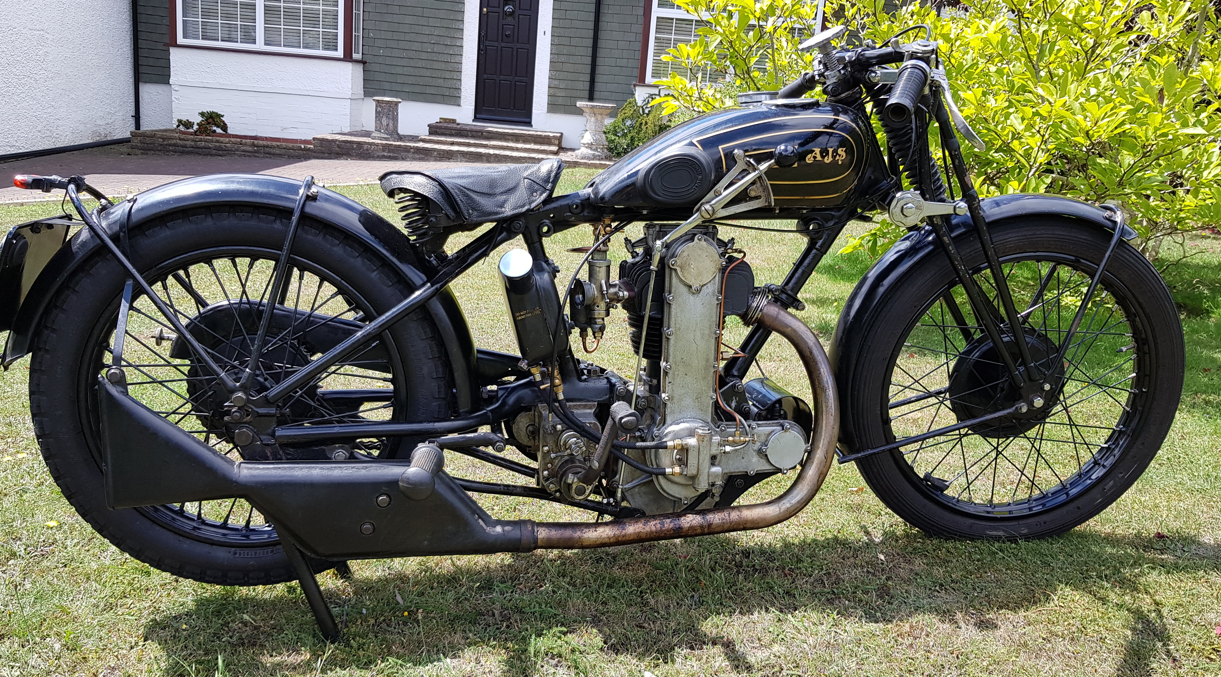
that I've been riding for many years and wanted an early 350cc bike. I bought one at a Bonhams auction; this is what I brought home....

....a bit of work was needed to bring it back to life 

Full details of the restoration can be found here.

During the restoration of the K7 I figured that I could put an early overhead camshaft Velocette cylinder, cylinder head and cambox onto the crankcases of an AJS 350cc engine from 1931, convert it to chain-driven OHC and make an engine that looks like a K7 but has a Velocette top-end. I had a 1928 350cc AJS sidevalve that I had bought on eBay and used that to create the AJcette ....giving credit to both manufacturers.

It looks pretty similar to the K7 and to demonstrate that there really are 2 bikes, here they are both together.


Details of the AJcette project can be found here.

I have quite a lot of early Mk1 OHC Velocette parts and after completing the AJcette I decided to use some of these to make a replica of a one-off bike that AJS built in 1929/1930 for an attempt on the world speed record. The original is a huge V-Twin beast that started out with a naturally-aspirated engine but, having failed to gain the record, was supercharged ...and again failed. The bike ended up in Tasmania for many years and, after being repatriated to the UK and restored, it is now in the National Motorcycle Museum.

This is what the original looked like:

and this is my recreation.


Like the AJcette, the V-Twin uses Mk 1 OHC Velocette cylinder components. The full story of how this bike was built can be found in the links here.

There is also a 14 minute edited Youtube summary of how these bikes came about here and a longer unedited version here

This bike is now in the Sammy Miller Museum.


In January 2022 I started the restoration of a 1933 AJS Trophy Model

and this was completed in March 2023.


The Index Page for this project can be found here.

I also reported briefly on a couple of my other projects ....vintage OHV Nortons


 and putting a Marshall supercharger onto my 1934 MG PA


I hope you find something of interest.

KTT 581: Engine Rebuild – Part 1 – The Bottom End

With the 2x KTTs and the 250 DOHC dry builds completed it was now time to give the engine of KTT 581 some TLC. It has been sitting forlornly on a bench in my workshop since last summer – you may recall that this

is what it looked like when I first received it. Some initial work was done – described here – but there was still plenty left to do to get the engine back into running order. I had postponed doing any further work because otherwise the dry builds of the other bikes would not have been completed and there would have been too many projects with open ends.

So, what is the plan? Before starting the painting and plating of the 3 Velos that are currently parked in my garage I have decided to rebuild the engine of KTT 581 before building the engine into the 1936 Mk2 KSS that I acquired last year (this will be a project for next winter).

The first part of the engine rebuild was to get the bottom-end sorted out; this was the starting point.


Although filthy dirty, the crankshaft turned smoothly

and so did the oil pump.

I originally planned to split the crankcases to clean everything but found it impossible to remove the crankshaft shock absorber assembly. I won’t go through all the details here but essentially this requires a tool with 4 pins to engage with the 4 holes of the LH threaded screwed collar (K-93) and to then hold the crankshaft stationary to unscrew the collar. I have a tool to engage properly with the collar and I can stop the crankshaft from rotating with a chain around the engine sprocket but I found it impossible to unscrew the collar – it was far too tight; clearly the parts have developed a strong attachment after being together for 91 years!

Not wishing to damage any of the assembly (which is working perfectly OK) I decided that I would instead clean the parts as thoroughly as possible without stripping. This involved masking and blanking off all openings (making an aluminium “cap” for the crankcase mouth) and brushing the entire structure with a brass wire brush on the aluminium and a steel brush on the shock-absorber to remove surface oxidation on the outside. I have not used vapour blasting because of the possibility of the small beads ending up inside.


The crankcases were then half filled with cellulose thinners and flushed out (twice), evaporating any residual thinners with a fan heater on the crankcases and an airline inserted into the drain plug hole to gently waft air through for a few hours and finally flushing out (twice) with fresh engine oil.

This has cleaned up the bottom-end inside and outside pretty well

and without causing any damage. The shock absorber has been lubricated externally.

It was now time to turn attention back to the piston. You may recall that there was some historical damage to the top land that was probably caused by someone in the distant past trying to remove the barrel and getting it stuck halfway.

After vapour blasting the piston and laser welding the damaged section

the ring groove has now been reformed by careful filing,


The piston/cylinder clearance was checked on the thrust/antithrust section at the bottom of the bore and found to be 0.009” – quite acceptable and the compression/oil rings gaps (new rings from Cox and Turner) at 0.012”/0.020” were also OK and so I could proceed with the build without having to make any adjustments.

When I stripped the engine there were 2 shims of 0.012” and 0.035” thickness between the cylinder and crankcase. I would assume these were put there either to get an exact target compression ratio or a desired valve/piston clearance. These were cleaned up and sandwiched between 2 new paper gaskets

before attaching the piston

and slipping the barrel on.

One observation I would make is that the con-rod was fully machined

and had been highly polished.

I checked the engagement of both the lower bevel and the magneto drive gear; I had not disturbed these from their original factory build and the meshing was perfect. It was not easy to photograph the 2 lower bevels with the K-34 magneto drive gear on the crankshaft but the drive gear engagement can be seen.

The oil pump driving piece, K-96, has the 2 discs behind it

as I mentioned in a previous blog. I have a parts list up to 1935 and that includes the Mk IV KTT but not the Mk V. There are some major differences between these engines – through-bolting of the cylinder (ie clamped at the cylinder head rather than bolted at the base flange), the lubrication system (using strategically-placed quills rather than pressurising the internals) ….and, although only a small detail, these 2 small discs are also not mentioned in the parts list for the Mk IV. Is there a parts list for a Mk V anywhere?

Before reattaching the end cover a new gasket was made by tracing around the intact old one

before cutting out with a scapel and hole punch.

The magneto was put onto its platform and the inner timing cover was screwed into place (the magneto must be put on at this stage of the build – it can’t be put on later) to complete the build of the bottom end.

Unlike earlier engines, the Mk V combines the K-48 and K-45 covers into one unit; it is a more substantial and complicated casting and it contains oil transfer holes and the crankshaft quill.

The original BTH TT magneto has been rebuilt by Paul at APL and the chain tension was checked before moving on to the top-end of the engine.